The preferences window has three tabs:
General-tab
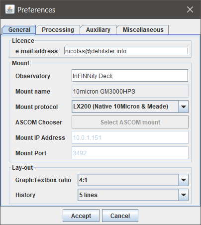
The General-tab allows activation of the
licence and setting of the
mount parameters and
program lay-out
Licence
The basic edition of MountMonitor only monitors RA and DEC. The registered version allows monitoring of an attached seismometer. For this an e-mail address should be provided, which is used for communication with the developer and to check the license status. When supplying an e-mail address the user is automatically informed of updates. For the basic functionality the e-mail address can be left blank and no internet connection is required. For the seismometer licence an e-mail address and internet connection (only required at start-up) are mandatory. When no internet connection is available MountMonitor automatically reverts to the basic mode at next start-up.
Mount
The fields
Observatory and
Mount name are recorded in the log and data files, but the latter of the two will be automatically retrieved from the mount once MountMonitor connects to the mount using
Mount IP Address and
Mount Port or using the ASCOM protocol. For the LX200 protocol (10Micron's and Meade's native protocol) the default 10Micron HPS port number 3492 is provided. When changing
Mount protocol to ASCOM, the
Select ASCOM Mount button is enabled, allowing to choose a mount ("telescope" in ASCOM terminology) using the ASCOM-Chooser. A pop-up will appear to warn that the Chooser will be opened, but that it will be somewhere in the background. Pressing OK followed by multiple [ALT][TAB] combinations should bring the Chooser-window to the foreground. In ASCOM mode the fields
Mount IP Address and
Mount Port will be disabled.
Lay-out
The
lay-out panel has the following settings:
Graph:Textbox Ratio
The Graph:Textbox Ratio sets the height of the
graphs in relation to that of the text boxes. A 4:1 ratio means that each graph is four times the height of the text boxes. Together the graphs will thus be eight times the height of the text boxes.
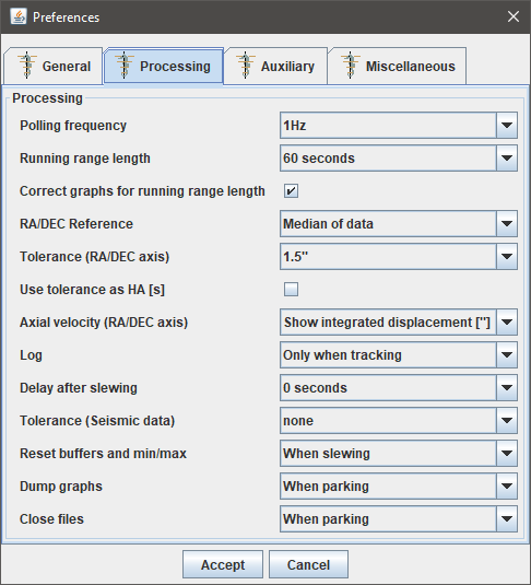
Processing-tab
The processing tab allows to change various settings used in the processing and displaying of data.
Polling Frequency
As per version 2.00 the polling frquency is the interval at which a whole interrogation sequence is repeated. As a sequence consists of four commands (status, time, RA and DEC), commands are sent to the mount at four times this frequency. The software dynamically adjusts the loop to meet the required polling interval even when network load increases or decreased. It depends, however, on the network connection speed, computer and mount whether polling frequencies above 3Hz can be achieved. When set at a too high value MountMonitor will run at maximum speed and the actual polling frequency is calculated from the number of sequences per time period (average of 100 sequences). The actual frequencies can be seen in the upper right hand corner of the
Fast Fourier Transformation window.
Running range length
This range in seconds defines the period over which the blue running standard deviation is calculated. Possible values are 60, 120, 300 and 900 seconds, which are equal to those used by 10Micron staff to analyse log files from their Mount Logger software. The running range is used for the STDEVs, the axial velocity and axial displacement graphs. As they are calculated for the past 60, 120, 300 or 900 seconds they show the data with this amount of delay. This delay can be dealth with using the following option:
Correct graphs for running range length
As the STDEVs, the axial velocity and axial displacement graphs are calculated for the past 60, 120, 300 or 900 seconds they show the data with this amount of delay. Enabling this option allows the graphs to be shifted in time:
- STDEVs: by half the length of the running average, so that the peak in STDEV is around the peak of the deviation;
- Raw axial velocity: by 3 observations, which is half the amount of observations used for this graph;
- Axial velocity: by half the length of the running average, so that the peak in axial velocity is about halfway the displacement;
- Axial displacement: by the full length of the running average, so that the peak in integerated displacement is around the peak of the measured displacement (in this way the integrated displacement should correlate with PHD2 measurements).
RA/DEC Reference
With this option the reference can be set for the right ascension and declination. When set to median, the reference will be the median of the data currently in view of the respective graphs. In Mount target coordinates mode MountMonitor will request the target coordinates at start-up and directly after each slew (at the end of the delay after slewing time). When using an ASCOM connection the target coodinates may not be available until the next slew after MountMonitor was started. So when a slew was given before MountMonitor was started (provided it runs in ASCOM mode), the target coordinates may not yet be available for MountMonitor.
Tolerance (RA/DEC axis)
The tolerance is the maximum that data is allowed to deviate from the median. When data or the running standard deviation exceeds this value a warning is given in the status window and stored in the log file. When the seismometer is connected an additional tolerance field is available which can be set to a percentage of the seismic range.
Use tolerance as HA [s]
The tolerance for the RA/DEC axis can be used in two ways for the RA axis: either in arc seconds or seconds of time. Enbaling the option
Use tolerance as HA [s] shows the tolerance levels as seconds of time, so at the same scale as the RA axis. Disabling the option shows the tolerances as arc seconds, while the tolerance lines in the RA-graph will be annotated with both the arc-second value and the value in seconds of time (the arc-second value divided by 15 and by the cosinus of the declination). Disabling the option allows to compare the RA-graph to the physical dimensions of a pixel on the imaging array.
Axial velocity (RA/DEC axis)
Using the
:GaXa# and
:GaXb# commands MountMonitor interrogates the orientation of the RA and DEC axis. When enabled MountMonitor waits for 100 samples to gather enough data to determine the axial velocity using a linear regression. Once running this linear regression expands until the
Running range length is reached. The resulting speeds are averaged using the same
Running range length routine. The resulting data can be displayed as axial velocity (annotated with
[x.xx"/s])or, by integration, as axial displacement. If this option is chosen, the graph is not only annotated with the displacement in arc seconds
[x.xx"], but also with the spherical displacement in arc seconds
[x.xx"SPH], which is the displacement multiplied with the cosine of the declination. This value is calculated in order to compare it to the size of a pixel (expressed in arc-seconds) on an imaging sensor. Due to the running range length the graphs are delayed by the length of the Running Average Length, but the
graphs can be shifted.
NOTE: despite waiting for 100 samples the first period defined in the Running range length can produce incorrect data, reliable data can be expected after at least twice this time.
Log
The Log menu allows to choose between All and Only when tracking. When the latter is chosen no data will be logged when slewing (e.g. during meridian flip). The status window shows when data is ignored. Using this setting, logging will commence after the waiting period set at Delay after slewing (see below).
Delay after slewing
This delay sets the time after a slew that MountMonitor will wait before logging starts or continues, this to avoid that last minor corrections in RA and DEC after the slew has ended are recorded.
History
History sets the amount of lines kept in the scrolling text blocks.
Reset buffers and min/max
This option defines how the buffers and min/max lines are reset. The options are
Manual and
When slewing. With the first option reset can be done through the reset menu, when set to
When slewing, the reset is automatically done when slewing is detected. The reset means that the
graphs are made blank and start empty once the slew is done.
Dump graphs
This option defines when the
graphs are saved to disc. The options are
Manual,
When slewing and
When parking. With the first option graphs are saved when
Reset/Buffers or
Reset/Buffers and min/max is chosen from the main menu. When set to
When slewing, the graphs are automatically saved when slewing is detected. The last option saves the graphs when parking. In all cases graphs are saved on exit.
Close files
This option defines when the data and log files are closed (and reopened). The options are
Manual,
When slewing and
When parking. With the first option
the files are closed when
Reset/New files is chosen from the main menu. When set to
When slewing, the files are automatically closed and new ones are opened when slewing is detected. The last option closes the files when parking. In all cases files are closed on exit.
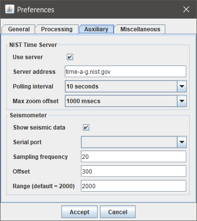
Auxiliary-tab
The Auxiliary-tab has two panels: the
Time-panel and the
Seismometer-panel (provided an e-mail address was entered in the
General-tab).
NIST Time Server panel
The
NIST Time Server panel has the following settings:
Use server
With this option connection to a NIST server can be switched on or off. When switched on a blue line will be added to the time-graph, showing the difference between the PC-clock and the NIST Time Server. If no internet connection is available or drops, this additional blue line disappears.
Server address
The address of the NIST Time Server (e.g. time.nist.gov). A list of available NIST Time Servers can be found
here (requires internet connection).
Polling interval
The interval at which the NIST Time Server is contacted. The default value is 30 seconds.
Seismometer panel
The
seismometer panel is only active if a
seismometer licence is acquired, the correct e-mail address is provided in the
licence field and an internet connection was present during start-up. The panel has the following settings:
Show seismic data
With this checkbox the additional seismic graph window can be switched off. The corresponding frequency or wave period graph in the
Fast Fourier Transformation window will remain active, provided that the
seismometer remains connected.
Serial port
The seismometer operates using an USB to serial analogue to digital converter (AD-converter). The serial ports pull-down list is populated each time the preferences dialogue is openened. The USB AD-cenverter can thus be connected while MountMonitor is running as long as the preferences dialogue is closed.
Sampling frequency
The sampling frequency is the rate at which the USB AD-converter collects data from the
seismometer. The default value is 20Hz. A proper setting is required for the length of the arrays that temporarily store the seismometer data. The actual frequency at which the data is collected is calculated by MountMonitor based on the number of samples found per time period. The actual frequences can be seen in the upper right corner of the
Fast Fourier Transformation window.
Offset
The offset is a fixed value added to the seismometer data to centre the data around zero. Default value is 300.
Range
The range is the maximum positive or negative value shown in the seismometer graph. A tolerance field is available in the
processing panel once the seismometer is connected, which can be set to a percentage of the seismic range.
Tolerance (Seismic data)
When the seismometer licence is active the processing box has an additional option to set the seismometer tolerance to a percentage of the seismic range. When data or the running standard deviation exceeds this value a warning is given in the status window and stored in the log file.
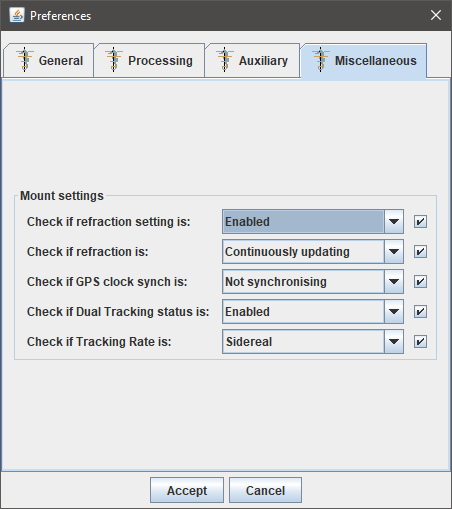
Miscellaneous-tab
The Miscellaneous-tab has one panel: the
Mount settings panel).
Mount settings panel
The
Mount settings panel currently has a variety of settings that can be used to check if they have been properly set in the mount. Enabling these settings makes MountMonitor to check at start-up and after every slew whether or not the mount has these options set as indicated by the options in their respective pull-down lists. If enabled an alert pop-up will warn the user to correct the setting. Both the warnings and the successful verifications are logged in the log file.
Check if refraction setting is
This check has two options:
Enabled (the software should check if Refraction Correction is enabled in the mount) and
Disabled (it should be disabled).
Check if refraction is
This check has three options:
Not updating,
Not updating while tracking,
Continuously updating, which all correspond to their respective settings in the mount's keypad.
Check if GPS clock synch is
This check has two options:
Not synchronising and
Synchronising, which correspond to their respective settings in the mount's keypad.
Check if Dual Tracking status is
This check has two options:
Enabled (the software should check if Dual Tracking is enabled in the mount) and
Disabled (it should be disabled).
Check if Tracking Rate is
This check currently has only one option:
Sidereal, but the software will check and warn for every deviation from sidereal tracking. When enabled the option verifies that:
- Follow object is OFF
- Tracking correction is set to 0.000%
- Tracking speed is set to Sidereal
When tracking speed is set to
Custom with a 0.000 rate for both axis it will still give a warning, despite tracking sidereal speed.