
1926 Zeiss RThII Theodolite Figure 1: The 1921 model Carl Zeiss RTh II theodolite from 1926 Strange how things can go when you use and collect older instruments. It was only last May (2011) when I found a famous theodolite designed by Heinrich Wild during his years as manager of the Geo department of Carl Zeiss, the 1924 Zeiss Th1.1 It was a special instrument as it was designed by Heinrich Wild before he started his own firm Wild Heerbrugg. The Th1 had several new design features not shown before on any other instrument and a few he had patented before and applied to a repetition theodolite, the Carl Zeiss RThII shown here. The RThII was produced between 1913 and 1945 and one from 1926 came up for sale this month on a Dutch on-line market place. Only two persons seemed to be interested in this seemingly old and little interesting instrument, one of them being me. Being an excellent instruction piece for my students (it is my first full repetition theodolite), my firm soon outbid the other person and the instrument ended up in the collection. The instrument was put on sale by a former employee of the architect's firm De Bruijn BNA in Wassenaar. He started his career with them as an apprentice draughtsman in February 1968. During their hey-days in the 1980s De Bruijn BNA employed some 25 personnel. Somewhere around 1970 De Bruijn took over a project from another architect's firm, Strik, as they were unable to continue their commitment. De Bruijn BNA took over their projects and inventory, among the latter came this RThII. The story has it that Strik was a former employee of architect Johannes Thomas Wouters (1866-1932) or of his son, architect W.C. Wouters3, and continued the latter's firm at some point in history. It is J.Th. Wouter's name that is stamped into the box twice (see figure 8) and once on the tripod. In 1996 architect's firm De Bruijn BNA discontinued their activities. The seller of the instrument started his own business and took over a part of their inventory, among which was this theodolite.  Figure 2: The RThII from the other side. Design features At the start of his career Heinrich Wild worked as an instrument maker and advisor for Carl Zeiss. He patented a wide variety of inventions related to geodetic instruments and this instrument is the first theodolite to show some of them.1,4 In total four patents can be found on the instrument and in his early levelling instruments like the Nivellier I and Nivellier II:
The model name RTh II stands for Repetitions Theodolit II (German for Repetition Theodolite). It is the first full theodolite of this kind in my collection, all the other I collected so far are reiteration theodolites. Only the Société des Lunetiers theodolite is a repetition theodolite, but without the capability to measure vertical angles. Whereas nowadays it is common practice to do reiteration (for those happy few that are still using theodolites), in the old days it was mainly repetition that was used in surveying. Another interesting feature of this theodolite is the fact that a clamping knob on the vertical circle allows it to use as a tilt type levelling instrument. For this the telescope is set at an angle of exactly 90 degrees. The knob directly next to the circle (see figure 3) is fastened, while the other knob on top (see figure 13) is left loose. Now the left vertical circle drive knob can be used to level the telescope using the coincidence vial, while keeping it locked in the 90 degrees position.  Figure 3: The knob below left of the centre is to clamp the telescope for levelling. Accuracy The 230 millimetres long telescope with 35 millimetres aperture gives an inverted view (see figure 19). The stadia hairs have a multiplication constant of 100 and an addition constant of 0.10 metres. The RThII was equipped with metal circles (120mm diameter horizontal and vertical) and four vernier reading telescopes (two for both circles). The RThII does not have a compensator for the vertical index, a large coincidence vial with an accuracy of 30 arc seconds per 2mm and a settling accuracy of 0.7" is used instead (see figure 3).6 This RThII has sexagesimal circles divided in degrees down to 20 arc minutes intervals (centesimal RThII's have been made as well) and can be read using a vernier directly to 2' and estimated to about 20-30".7 The circles are illuminated using white reflectors (see figure 4 and figure 16). Production The RThII was produced at Carl Zeiss Jena between 1913 and 1945.8 Between 1913 and 1943 some 750 instruments were made.8 Compared to about 7,000 T3's and 40,000 T2's produced by Wild Heerbrugg in a 45 year period this is a very limited number of instruments. Even compared to the 1000 ThI's it still is a limited amount.  Figure 4: The horizontal circle is illuminated using this opening in the telescope tube. The serial number on the instrument indicates that this particular one was produced in 1926, which is confirmed by the label in the lid (see figure 7). With the tripod stamped with the same name as the box it is quite likely that the tripod originally was bought together with the instrument. Another indication for this is the fact that the tripod is made completely of non-ferrous materials, while the RThII was intended as a boussole theodolite. With tripod, but without boussole the RThII would have cost RM1110,- in 1926 (RM = Reichsmark). The boussole would have added another RM90,-. That same year the Th1 would have cost RM1410,- without and RM1510,- with boussole.9 Although a space for a boussole is present in the box of the RThII in my collection, it is uncertain if it was ever delivered with one as no records were kept whether they were delivered with or without them.8 The latch that would keep it in place does not show any wear on the inside, which may indicate that it was delivered without one or that the boussole got separated in a very early stage. Notes: [2]: With many thanks to J. Korpershoek for his elaborate historic details. [3]: Bouw 1961, vol. 16, no. 1, p. 35: An announcement was made in this bulletin that, at an age of 63, Ir. W.C. Wouters of the architectural firm bearing that same name had passed away in Wassenaar. [4]: D.A. Wallis, 'History of Angle Measurement', in: International Federation of Surveyors, FIG, (2005), p.12. [5]: With many thanks to John Bradley for pointing this following out to me: Invented in 1770 by Johann Mayer, circular vials were already in use before that time, but mainly to roughly set levelling instruments, rather than theodolites, although Breithaupt already made a boussole theodolite in 1818 using a circular level. Earlier examples of detachable tribrachs can be found in J. Butler William's 1855 book Practical Geodesy. For circular levels and their early application on instruments, see M. de Vos, Leerboek der Lagere Geodesie ... met 196 figuren in den tekst., (Groningen, 1905), pp. 26, 145. [6]: Carl Zeiss - Jena, 'Theodolite, Model No. I with automatic reading mean reading, conjoint reading, and optical micrometer.', in: Carl Zeiss - Jena, Leaflet: Geo 33, (1924). [7]: Carl Zeiss Jena, Druckschrift Geo32, 1924. With many thanks to Dr. Wolfgang Wimmer and Ms. Marte Schwabe of the Zeiss Archives for sending me a digital copy. [9]: Carl Zeiss Jena, Druckschrift Geo54a, 1926. With many thanks to Dr. Wolfgang Wimmer and Ms. Marte Schwabe of the Zeiss Archives for sending me a digital copy. If you have any questions and/or remarks please let me know. |
 Figure 5: The instrument came in its original box. |
 Figure 6: A close-up of the picture on the door of the box. |
 Figure 7: A label explaining how to pack the instrument and a note how to level with it. |
 Figure 8: The box came with its original Zeiss key. |
 Figure 9: The instrument is a repetition theodolite. |
 Figure 10: The base is inserted into the tribrach, similar to later Zeiss models and the Askania. |
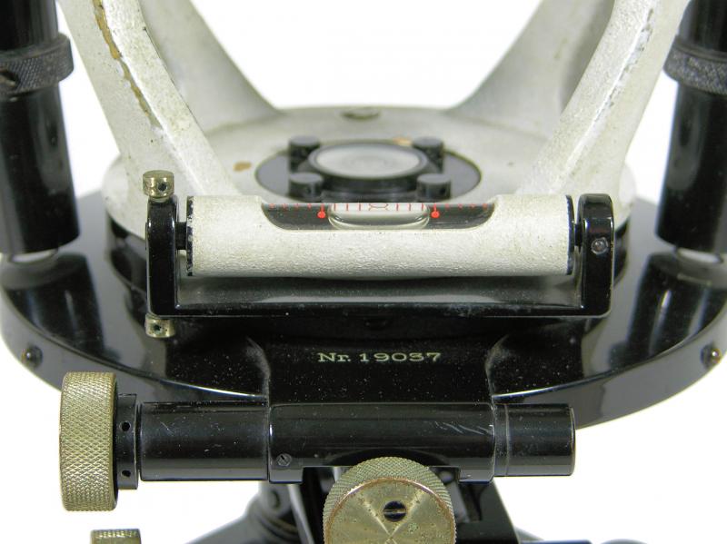 Figure 11: The plate vial of the RThII. |
 Figure 12: 'D.R.P.' (Deutsches Reichspatent) and 'D.R.G.M.' (Deutsches Reichs-Gebrauchsmuster) |
 Figure 13: The instrument is recognised by the two balance bodies on the secundary axis. |
 Figure 14: The RTh II (right) compared to the Zeiss Th1 (left). |
 Figure 15: The vertical vial next to the vertical circle. |
 Figure 16: The vertical circle is illuminated by discs at the end of the reading telescopes. |
 Figure 17: The vertical reading 61°-32'-30'' and just over 241°-33'-00''. |
 Figure 18: The horizontal circle reading just under 112°-34'-00'' and 292°-33'-30''. |
 Figure 19: The inverted view through the telescope. |
 Figure 20: Coarse aiming is done using this adjustable bead. |
Surveyor's crosses... Geodetic Sextants... Theodolites... Total Stations... Levels... Standards... Tools... Firms...
19th c. SDL 1919 K&E 1926 Zeiss RThII 1924 Zeiss Th1 1929 Wild T2 1937 Wild T3 (astronomic) 1939 Wild T3 (geodetic) 1943 CT&S Tavistock 1948 Wild T1 1950s Askania Tu400 1952 Wild RDH 1956 Wild T0 1960s Zeiss BRT 006 1961 Wild T1A 1961 Wild MIL-ABLE T2 1962 Wild T2 1963 Wild RDS 1966 Kern DKM2 1969 Wild T2E 1969 Wild Di10 / 1972 T2 1976 Wild Di3S / 1963 T2 1976/79 Wild T2 mod - DI4 1990 Wild T2 mod - Di1000